Table of Contents
Yodeck player based on Raspberry Pi
⚠️This section is available only for players based on Raspberry Pi. For other player types, this section won’t be displayed at all. Here are some more details about the Yodeck Player based on Raspberry Pi.
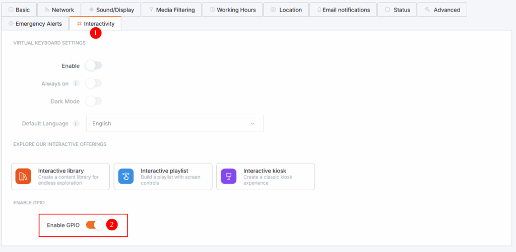
The option to enable General-Purpose Input/Output (GPIO) can be located under the Interactivity section.
GPIO Reference
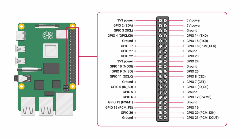
Below is the Raspberry GPIO pinout, sourced from the official Raspberry Pi documentation.
GPIO Schematics
In the first image, the physical numbering of GPIO pins is mapped to the type of each pin.
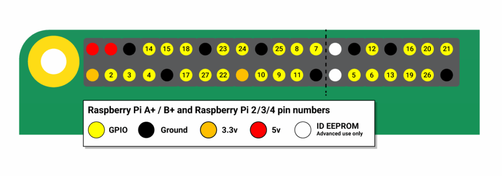
In the second image, GPIO pins are directly mapped with their Broadcom-specific numbering (BCM), which is the numbering convention used by our API.
Known limitations
The GPIO board operates under certain limitations and assumptions that must be respected for any use, to avoid inconsistent behavior or hardware damage.
- The GPIO board can handle a maximum current of 16mA per pin and 51mA for the entire board.
- Exceeding these limits may result in permanent hardware damage.
- The Raspberry Pi includes a self-healing fuse that may help avert damage in case of hardware misconfiguration. However, it is not guaranteed to prevent every possible damage or to heal properly afterwards. Therefore, we advise caution with the circuit design.
- Exceeding these limits may result in permanent hardware damage.
- The pins
GPIO 0andGPIO 1- These are reserved for I2C communication with an EEPROM and are primarily targeted at HAT use. Please refrain from using them.
- The pins
GPIO 2andGPIO 3- They are intended for I2C use and have a fixed pull-up resistor, without the ability to be configured for pull-down behavior. Please refrain from using them unless the external circuit is compatible with pull-up logic.
For an interactive map of GPIO pins and their use, you can also refer to https://pinout.xyz
Intended Use Cases
Our GPIO API supports local HTTP requests that expose the low-level GPIO API to HTML5 Custom Apps. You can find more details here.
The current functionality returns the current state of the GPIO pins upon request from the App. Therefore, optimal use cases should include logic that relies on GPIO state (turned-on switch) rather than GPIO events (button-press).